Jtag Circuit Diagram
Zcu102 digilent usb-to-jtag module, circuit, pictures and diagram Jtag info Jtag cortex connector wiring arm schematic circuit microcontroller consensus proper reset nxp pins jumper stack
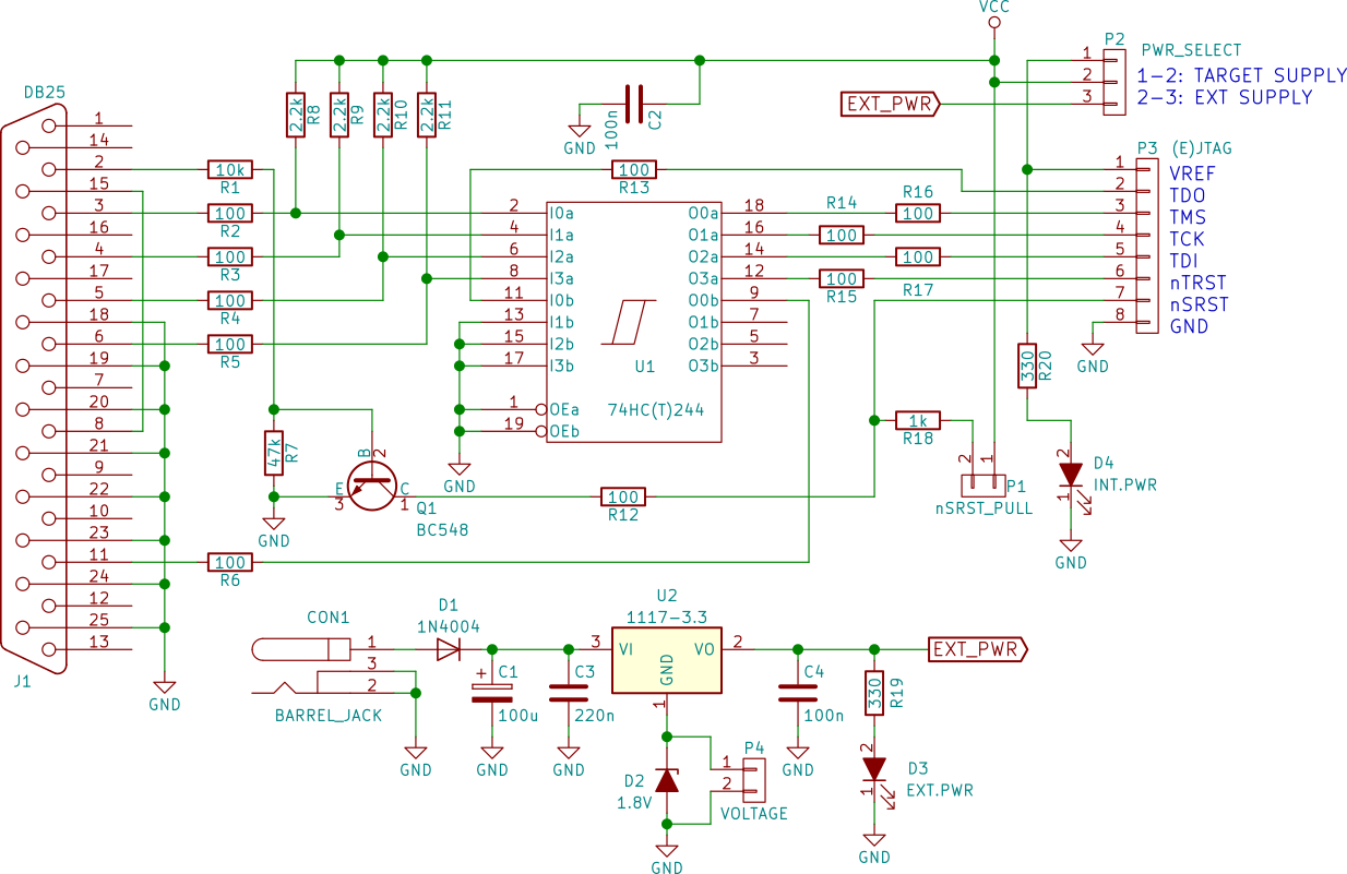
Make a buffered JTAG adapter (Wiggler) · One Transistor
Jtag interface Jtag — maple v0.0.12 documentation Jtag interface schematic diagram.
Jtag tdo working custom board ti e2e microcontrollers
Jtag altera circuit interface diagram debug projectsJtag traverse debugging Jtag scan boundary semiconductor testing joint test action group devices toshiba storage organization which standardizes originally pc name[solved] cortex-m jtag connector interface. differences between texas.
How to check whether the fpga pin of the jtag port is broken?Jtag linksys pinout wrt54g v2 usb hardware info tiny Make a buffered jtag adapter (wiggler) · one transistorJtag xjtag scan boundary testing test protocol use make port debug programming tutorial register access bsr four underlying communications wire.

Jtag parallel universal usb manual user port layout power utilizes provides pw 5v output 100ma remember which only default board
Jtag schematic wiggler buffered adapter makeJtag nxp Jtag connector schematicJtag programmer sigma lpt interface.
Universal jtag user manual (parallel)Jtag interface Jtag ice usb atmel schematic avr microcontrollers board ro chooseJtag pcb 1149 ieee.

Jtag connection header pcb microcontroller schematic diagram schematics instruments texas programming
Jtag fpga port circuit fpgakeyTypical board with jtag components – pcb Jtag proposedWhat is jtag and how can i make use of it?.
Jtag (boundary scan)Jtag wiring diagram maple arm port standard docs connect pub static Typical jtag connector diagramJtag interface schematic diagram..
![[SOLVED] Cortex-M JTAG connector interface. Differences between Texas](https://i2.wp.com/forum.segger.com/index.php/Attachment/2571-JTAG-TM4C12x-guide-jpg/)
Jtag docs udoo neo
Kmtronic ltd: jtag programmerJtag router Texas instrumentsSolved: board bringup.
Debrick routers using jtag cableJtag connection segger cortex interface connector ti pull tck tms tdo tdi schematic forum resistor e2e Ls1088 jtagJtag digilent.

Jtag bus description and pinout
Jtag connection used in the proposed designAvr jtag isp circuit kanda schematics layout way schematic Jtag headerJtag bus scan description pinout device ieee 1149 test signal diagram block.
Usb jtag ice for atmel avr microcontrollers – emmd labAltera jtag download and debug interface circuit |circuit diagram projects [resolved] jtag (tdo) not working in custom boardJtag interface schematic diagram..