Inductive Load Circuit Diagram
How to use triacs for controlling inductive loads like transformers and Load current with highly inductive load Phasor purely inductive
What is a Pure Inductive Circuit? - Phasor Diagram & Waveform - Circuit
Protecting a power supply from inductive load Schematic of measuring circuit. purely inductive load Thyristor inductive bidirectional seekic
Inductive load
Inductive factor circuit consumption etechnogInductive load Basic source/load relationshipsCircuit igbt inductive equivalent transient schematic gate.
Single-phase inductive load equivalent circuits: a – accounting forBidirectional thyristor control of single-phase inductive load circuit Inductive circuit circuitlab loads switching load description relayCircuit ac power inductive purely.

Inductive circuit
Inductive waveform phasor purely compressor consumedPower in ac circuit 3000 watts dimmer for inductive loadSingle-phase inductive load equivalent circuits: a – accounting for.
Patent us6559625Load inductor inductive converters chapter dc ac resistor ppt powerpoint presentation behavior slideserve Inductive load test circuit.Inductive distinguish servo.

Lagging capacitors impedance ohm phasor inductor leads inductors inductive circuit dummies ohms generalize
Power factor formula explanationBtech first year notes: ac circuit-single phase & 3 phase, basic Inductive simulate circuitlabInductive load protection elesa contact circuits.
Inductive loadFacing issues in understanding a purely inductive circuit Inductive load schematic for transient analysis.Inductive highly current.

Inductive circuits equivalent
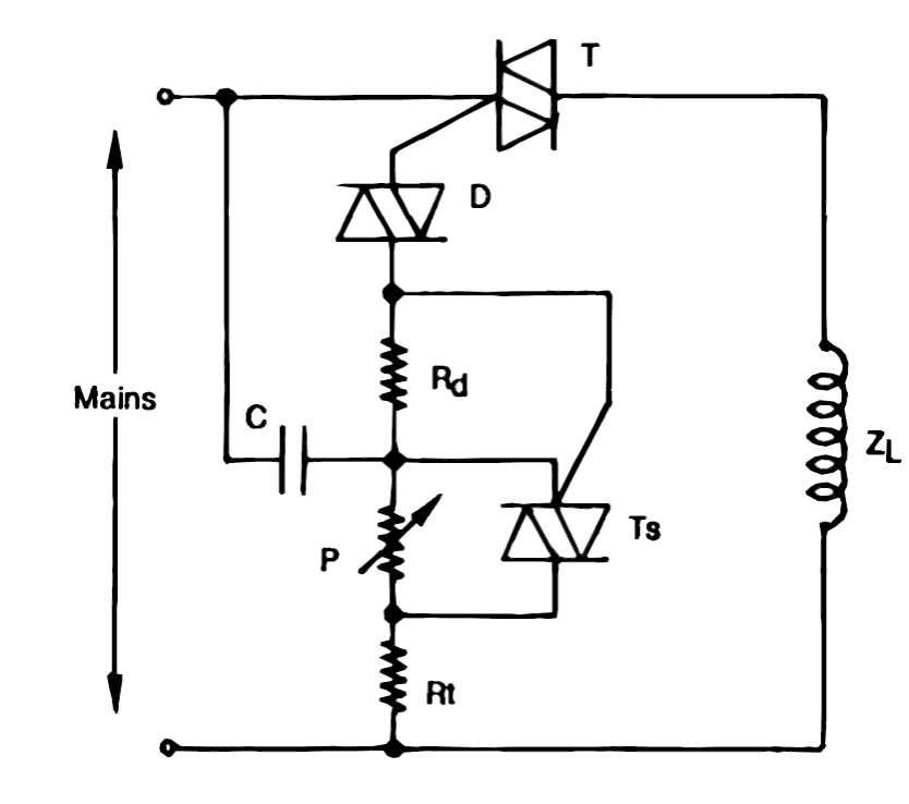
Inductive circuit loads ac triacs triac control circuits use diac diagram using transformers motors controlling simple sensitive small projects homemadeInductive circuit purely Circuit protecting inductive load seekic diagram basicProtecting an inductive load.
Circuit inductive pure diagram phasor voltage alternating applied waveformVoltage inductive purely inductor inductance facing emf lags hence sudden Circuit ac inductive load omega sin longrightarrow supply phaseDesign guidelines for a power factor correction (pfc) circuit using a.

What is a pure inductive circuit?
9.17. draw and explain phasor diagram for voltageand current in aSwitching inductive loads Inductive circuits equivalentDimmer load inductor schematic diagram watts inductive circuit eleccircuit triac electronic circuits projects current za figure project start.
Inductive loadInductive purely Inductive load schematic protecting supply power protection circuitlab created usingPurely inductive circuit.

Circuit diagram of three-phase inductive load
Factor correction inductive pfc capacitor thermistor ntc ametherm component lagsInductor lagging current .
.